Picture three-phase power humming at 400 V, 32 A per phase, pushing up to 22 kW into your EV. You cut 60–100 kWh battery charge times to ~3–5 hours with Mode 3, Type 2 hardware that meets IEC standards, with MID metering, OCPP, ISO 15118 Plug&Charge, DC-sensitive RCDs, load management, Wi‑Fi/BLE, and secure updates. But can your supply, wiring, and vehicle actually deliver that throughput?
Key Takeaways
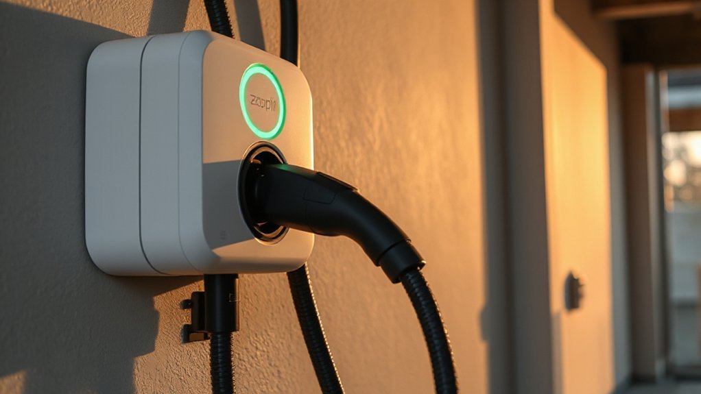
- 22 kW AC Mode 3, Type 2, IEC 61851-1 / IEC 62196-2 compliant.
- Three-phase 400 V at 32 A per phase; actual rate limited by vehicle onboard charger, often to 11 kW.
- Charges 60–100 kWh batteries in roughly 3–5 hours when the vehicle supports full 22 kW AC.
- Safety and durability: RCD with 6 mA DC detection, EN 61000 EMC, IP54–IP65 weatherproofing, IK10 impact rating, MID-certified metering.
- Smart features: OCPP 1.6J/2.0.1, ISO 15118 Plug&Charge, Wi‑Fi/BLE, app scheduling, OpenADR demand response, dynamic load sharing.
What Is a 22 Kw EV Charger?

How does a “22 kW” EV charger fit into the standards landscape? You’re looking at an AC supply device rated 22 kilowatts continuous output under IEC 61851-1, Mode 3, using IEC 62196-2 interfaces. To deploy it, you specify overcurrent protection per IEC 60364-7-722, residual-current protection with 6 mA DC detection, and EMC compliance to EN 61000 series. For revenue-grade billing, select MID-certified metering (EN 50470) and OCPP 1.6J or 2.0.1 for backend control; add ISO 15118 if you require Plug&Charge. In North America, target UL 2594, UL 2231-1/-2, FCC Part 15, and suitable NEMA enclosures. You’ll document IP54–IP65 and IK10 ratings. Market adoption depends on certification scope, grid-code alignment, cybersecurity profiles, and clear warranty terms quantified by years and kWh throughput, and serviceability metrics.
Three-Phase Power, Speed, and Vehicle Compatibility

Building on the 22 kW Mode 3 spec, that rating assumes 3-phase 400 V (line-to-line) at 32 A per phase per IEC 61851-1 and IEC 62196-2 Type 2. At unity power factor, that yields 22.1 kW real power; derate for cable temperature, voltage sag, and pilot-current limits. You’ll see charge times of roughly 3–5 h for 60–100 kWh packs, assuming the onboard charger supports 3×32 A. Many vehicles cap AC intake: 11 kW (3×16 A) and 7.4 kW (1×32 A) common. If your car is single‑phase, the station supplies one phase; Phase conversion to boost power isn’t allowed by most onboard chargers. Verify pin-out per IEC 62196-2, coding via 61851-1. Confirm Thermal management: 6 mm² conductors, <1.5 V drop, IP54 enclosures, and derating curves.
Smart Features and Connectivity Options

You’ll require Wi‑Fi (IEEE 802.11n/ac with WPA2/WPA3) and Bluetooth LE 5.0 for commissioning, firmware updates, and resilient local fallback connectivity. Using the OEM app, you configure charging schedules in 15‑minute increments aligned to TOU tariffs, set amperage limits, and enable demand response via OpenADR 2.0b where available. You also verify interoperability with OCPP 1.6J/2.0.1 and, when applicable, ISO 15118 smart charging to provide secure telemetry, remote control, and grid‑aware load management.
Wi‑Fi and Bluetooth


Why do modern EV chargers integrate both Wi‑Fi and Bluetooth? You need dual radios to balance throughput, Signal range, and resilience against Interference sources. Wi‑Fi (IEEE 802.11n/ac, 2.4/5 GHz) provides high bandwidth, firmware delivery, and secure TLS 1.2+ backhaul. Bluetooth LE (5.0/5.1) enables low‑energy provisioning, proximity authentication, and fallback when WAN’s down. For residential installs, specify WPA3‑SAE, disable WEP/TKIP, and prefer DFS‑aware 5 GHz channels. For multi‑dwelling units, design for -65 dBm RSSI, <2% PER, and survey for microwave, DECT, and neighboring APs.
| Feature | Spec |
|---|---|
| Wi‑Fi bands | 2.4 GHz, 5 GHz, DFS support |
| Wi‑Fi security | WPA3‑SAE, TLS 1.2+ |
| Bluetooth version | LE 5.0/5.1, PHY Coded |
| RF metrics | EIRP ≤ 20 dBm, PER <2% |
Use MIMO 2×2 antennas, IP54 enclosures, and maintain 30 cm separation from metal.
App Control and Scheduling
How should app control and scheduling work on a modern EVSE? You should get standards-based controls mapped to OCPP 1.6J/2.0.1 and IEC 61851 setpoints, with ISO 15118 support for SoC-aware schedules. Define Recurring Routines with 15‑min granularity, TOU tariffs, max current (A), energy caps (kWh), and cost ceilings. Enforce User Permissions via RBAC, OAuth2, TLS 1.2+, and optional MFA. Allow demand response via OpenADR 2.0b and dynamic current derating. Provide secure time sync (NTP), signed updates, and offline fallbacks using last policy. Expose APIs and webhooks, export CSV logs, and maintain audit trails. Let you pause/resume, lock connector, authorize RFID, and set per‑vehicle profiles. Validate metering (MID Class B), and verify schedules before execution. Support calendars, holidays, daylight saving shifts, and localization settings accurately.
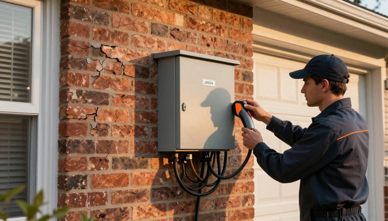
Installation Requirements, Wiring, and Safety Standards

You verify service and panel capacity: calculate EVSE continuous load (e.g., 7.7 kW @ 240 V = 32 A; 19.2 kW = 80 A), apply the 125% continuous-load rule (NEC 625.41/210.20(A)), and confirm breaker/bus ratings with ≤3% branch-circuit voltage drop. You size conductors per NEC 310/IEC 60364-5-52 at 75°C terminals, provide equipment grounding per NEC 250/IEC 60364-5-54, bond all metallic enclosures, and target grounding electrode resistance ≤25 Ω. You implement residual protection: NEC—EVSE with integral GFCI per 625.22/UL 2231; IEC—RCD Type A with 6 mA DC detection (IEC 62955) or Type B, IΔn ≤30 mA.
Panel Capacity Requirements
Before adding an EVSE, verify the service and panel can carry the additional continuous load per NEC 625 and 220. A 22 kW Level 2 at 240 V draws about 91.7 A continuous; size the branch circuit and feeder at 125%: ≥115 A, typically a 125 A breaker with 75°C conductors sized per Table 310.16. Confirm service/load calculations (NEC 220, Parts III/IV) leave sufficient capacity, keeping the bus and main within rating and typical 80% loading practices. Maintain voltage drop ≤3% branch, ≤5% feeder+branch at full charge current. Verify panel AIC rating ≥ available fault current. Provide enclosure space for heat dissipation. Reserve spare spaces and capacity for future expansion (e.g., second EVSE), and maintain working clearances per 110.26. Label the circuit per 110.22.
Grounding and RCDs
While EVSE includes internal protection, you must provide a low-impedance grounding and residual-current protection scheme that meets code trip thresholds and clearing times. Use a grounding electrode system ≤1–2 Ω and verify disconnection times per IEC 60364-4-41 and 60364-7-722. Install Type A RCD with 30 mA AC and 6 mA DC detection or Type B where DC leakage is possible. Coordinate with NEC 625/250. Test RCD trip time periodically ≤300 ms at IΔn and ≤40 ms at 5×IΔn. Bond enclosures, use 10 AWG or larger EGC for 22 kW circuits. Document tests, labels, and maintenance intervals.
| Item | Spec |
|---|---|
| System type | TN-S/TT, no PEN at vehicle |
| RCD type | Type A+6 mA DC or Type B |
| Ground impedance | ≤2 Ω verified |
| Notes | lifespan prediction, environmental impact |
Load Management, Energy Tariffs, and Cost Optimization

Orchestrating EV charging loads under dynamic tariffs minimizes OPEX and grid impacts. You implement load management using IEC 61851 current limits, OCPP 1.6/2.0.1 smart charging profiles, and ISO 15118 scheduling. Track feeder capacity and set a dynamic site limit (e.g., 50 kW), then allocate per-connector setpoints so a 22 kW EVSE ramps from 6–32 A per phase based on available headroom. With dynamic pricing and demand response signals (OpenADR, IEEE 2030.5), you shift energy to low TOU windows, cap coincident peaks, and avoid demand charges. Use state-of-charge and departure-time inputs to compute least-cost kWh via MILP or heuristic algorithms. Log interval data (15 min) for M&V, and verify compliance with grid codes, phase balance, and THD (<5%). Audit safeties and cybersecurity per IEC 62443.
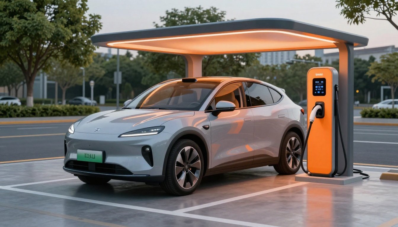
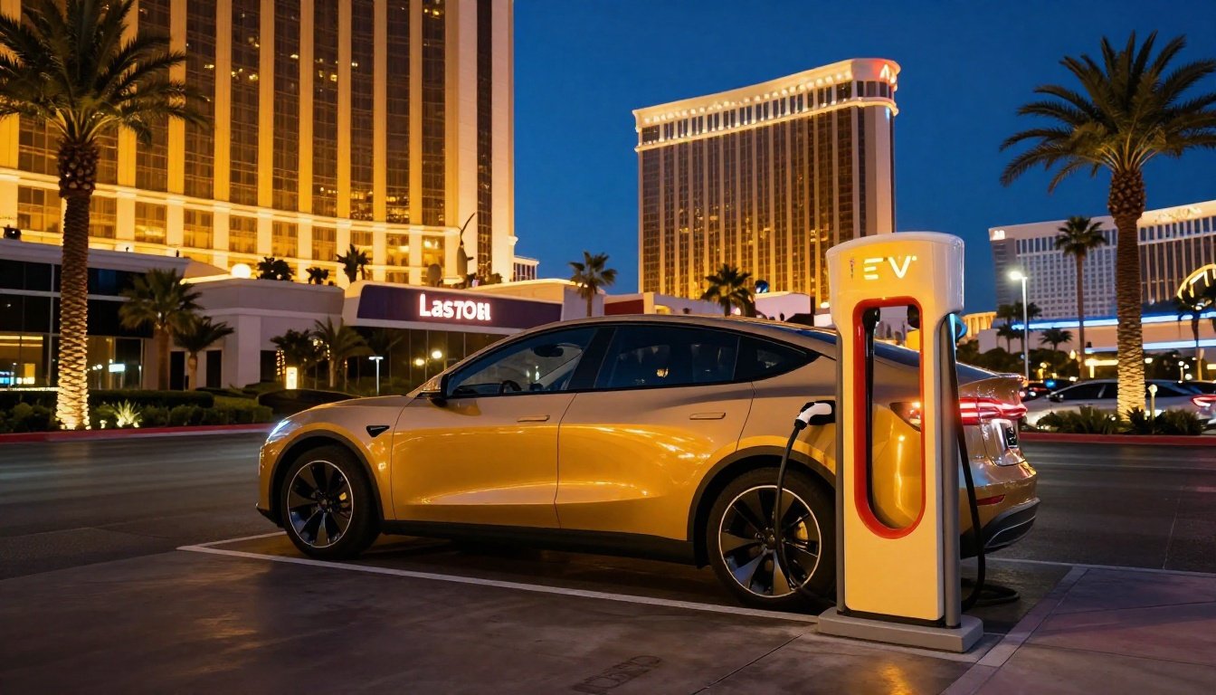
Use Cases for Homes and Businesses

Home-and-business deployments span single-family Level 2 EVSE (240 V split-phase, 32–80 A, 7.7–19.2 kW) and commercial sites (11–22 kW three‑phase AC and 50–350 kW DCFC) with standards-driven controls. You’ll specify OCPP 1.6/2.0.1 networking, ISO 15118/Plug&Charge, and IEC 61851 signaling for interoperability. For homes, you’ll prioritize load sharing, TOU optimization, and NEC 625 compliance. For businesses, you’ll address demand charges, RFID/payment, access, fleet integration, and destination charging analytics. Plan cable management, SLAs, and cybersecurity.
| Site | Power | Standards/Notes |
|---|---|---|
| Single-family | 7.7–19.2 kW AC | NEC 625, UL 2594; load sharing; Wi‑Fi/OCPP |
| MURB/Workplace | 11–22 kW AC | OCPP; ISO 15118-ready; access control; billing |
| Retail destination | 22 kW AC + DCFC | PCI/RFID; uptime KPIs; wayfinding; analytics |
| Fleet depot | 22 kW AC + 150 kW DC | OCPP 2.0.1; smart charging; V2G pilots |
Conclusion
You get more than speed with a 22 kW, three‑phase (400 V, 32 A/phase) Mode 3, Type 2 charger—you get a standards‑compliant backbone. IEC 61851/62196 hardware, MID metering, DC‑sensitive RCDs, OCPP 1.6/2.0.1, and ISO 15118 Plug&Charge harden uptime and billing. Worried it’s overkill? Dynamic load control and tariff scheduling cap demand, cut €/kWh, and protect the main fuse. It’s future‑proof for 60–100 kWh EVs across homes, fleets, and light commercial sites, today and tomorrow alike.