Over 80% of EV charging happens at home, and a 240V circuit can cut charge time by 3–4x. You’ll choose NEMA 14-50 vs 6-50, verify panel capacity, and size a 50A breaker with 6 AWG copper under NEC’s 125% continuous-load rule. Pull permits, follow GFCI and clearance rules, and weatherproof outdoors. If panel work worries you, a licensed electrician avoids hazards—but there’s a smarter way to future‑proof.
Key Takeaways
- Choose NEMA 14‑50 or 6‑50; both charge Teslas identically at 32 A with Mobile Connector; 14‑50 includes neutral, broader compatibility.
- Use a 50 A dedicated circuit with 6 AWG copper, sized for continuous load (80% rule), and a listed, panel‑compatible 2‑pole breaker.
- Pull permits, perform NEC 220 load calculation, and provide GFCI protection for garage/outdoor 240 V receptacles; label the circuit “EV Charging.”
- Install conduit and a mounted box 18–48 inches high; verify voltage/polarity, torque terminations, and pass inspection before charging.
- Set the Tesla charge current to 80% of breaker rating, monitor voltage/heat, and schedule charging off‑peak to minimize costs.
Choosing the Right Outlet: NEMA 14-50 Vs 6-50

Which makes more sense for your Tesla charging—NEMA 14-50 or 6-50? You’ll get identical charging speed with either when using Tesla’s Mobile Connector (32A). A 14-50 includes a neutral; a 6-50 does not. Since EVSE is a 240V load, the neutral isn’t used, so 6-50 is often simpler. However, 14-50 maximizes compatibility with RVs and ranges, and fits a broader adapter ecosystem. Choose a 50A circuit, copper 6 AWG conductors, and a properly listed receptacle. Continuous load rules limit you to 40A on 50A; that’s compliant for 32A. Install GFCI protection per NEC 210.8 and 625 for garage or outdoor locations. Verify enclosure rating, cord strain relief, and clearances. Consider Plug aesthetics and cord routing. Label the circuit “EV Charging” at receptacle and cover.
Assessing Electrical Panel Capacity and Load Calculations

Determining panel capacity starts with a dwelling-unit load calculation per NEC 220. Identify general lighting loads (3 VA/ft²), small-appliance and laundry circuits, fixed appliances with nameplate ratings, HVAC using noncoincident demand, and your EVSE as a continuous load at 125%. Apply the Article 220 demand factors to compute service load, then compare it to the service rating and panel bus ampacity.
Perform Label verification: confirm the panel’s bus rating, main breaker size, conductor sizes, and maximum breaker fill. Verify the EV branch spaces and that the panel is listed for the intended backfed or main configuration. Conduct a Thermal inspection under typical load; hot spots indicate loose terminations. Confirm working clearances, bonding/grounding continuity, and torque terminations to manufacturer specs. Document readings and calculation results.
Selecting the Correct Breaker and Wire Size

You start with load calculation basics: confirm your EVSE’s continuous current and apply the NEC 125% rule to set the circuit amperage. You then match the breaker to that value (e.g., a 50A breaker for a 40A EVSE), using a listed, panel-compatible breaker type. You select conductor gauge with ampacity at or above the breaker rating, accounting for copper vs aluminum, 60/75°C terminations, insulation type (THHN/THWN-2), ambient temperature, and voltage drop.
Load Calculation Basics
Before installing a 240V outlet for your Tesla, calculate the continuous load so you can size the breaker and conductors correctly per code. Treat EV charging as a continuous load at 125% of nameplate current. Determine the EVSE’s maximum current setting, not just the outlet rating. Add coincident household loads that may run simultaneously, considering startup currents and seasonal variations. Verify service capacity, feeder ratings, and panel space. Apply ambient-temperature and conductor-bundling adjustment factors per NEC tables. Evaluate circuit length for voltage drop; target less than 3% at full load under worst-case conditions. Use copper or aluminum ampacity from the correct column for insulation rating.
- Measure actual EVSE current setting
- Account for coincident loads
- Apply temperature and bundling corrections
- Check voltage drop over distance
Breaker Amperage Matching
With the load established, match the breaker and conductors to the EVSE’s maximum continuous current at 125% per NEC 210.19(A)(1), 210.20(A), and 625. Use a breaker whose rating equals or exceeds that 125% value, ensuring terminations are listed for the chosen temperature rating. Verify Trip coordination with upstream overcurrent devices, and account for Ambient derating for panel location and conduit fill. Select a 2-pole breaker listed for the receptacle configuration and GFCI where required. Confirm the breaker’s interrupting rating meets available fault current.
| EVSE nameplate (A) | Minimum breaker (A) |
|---|---|
| 16 | 20 |
| 24 | 30 |
| 32 | 40 |
Label the circuit, verify receptacle rating matches the breaker, and torque all terminals to the manufacturer’s specifications. Document test results and permit approvals before energizing for records.
Conductor Gauge Selection
Sizing conductors for a 240V EVSE starts by treating the EV load as continuous and applying 125% to the EVSE nameplate, then selecting a breaker and wire gauge whose ampacity (after all adjustments) meets or exceeds that value. Confirm conductor material, insulation type, terminal temperature rating, and derating for ambient temperature and conduit fill. Limit voltage drop to ~3% on long runs; upsize as needed. Match breaker to corrected conductor ampacity; protection never increases wire capacity. Typical 40 A EVSE uses a 50 A breaker with 6 AWG copper THHN-2; verify local amendments.
- Use 75°C column when terminations are 75°C; otherwise 60°C.
- Apply NEC 310 for >3 current-carrying conductors.
- Aluminum needs larger gauge; torque lugs, antioxidant.
- Label dedicated EVSE branch; avoid shared loads, circuits.
Permits, Inspections, and Code Requirements (NEC/GFCI)

Although a Tesla will charge from a simple 240V receptacle, you still need a permit and inspection from your local authority having jurisdiction (AHJ) to verify compliance with the NEC. The AHJ may require plan review, load calculations (NEC 220), and a dedicated branch circuit sized for a continuous load at 125% (NEC 210.20(A), 625). Provide GFCI protection for 125–250V receptacles in garages and outdoors (NEC 210.8); label the breaker “EV Charging” (NEC 110.22). Use listed devices, apply torque to terminations (NEC 110.3(B), 110.14), and select proper enclosure ratings, e.g., NEMA 3R outdoors. Maintain working clearances at panels (NEC 110.26). Expect final inspections verifying conductor size, overcurrent protection, and receptacle configuration. Preserve permits, inspection cards, and manufacturer instructions for Record Retention. Confirm Local Variances.
DIY or Licensed Electrician: How to Decide

Assess your skills against the risks: working in panels, calculating a continuous EV load (125%), sizing conductors/breakers, and ensuring fault/grounding protection. Verify permit and inspection requirements and comply with NEC 210, 625, 250, and 110.3(B), including GFCI in garages and proper labeling. If you’re not fully competent with 240V circuitry and code coordination, hire a licensed electrician.
Skill and Risk


Before you pick up tools, decide whether to DIY or hire a licensed electrician by weighing code scope, your skills, and the risks. Assess whether you can calculate load, size conductors, terminate a NEMA receptacle, and verify grounding and GFCI/AFCI requirements. If you don’t routinely work energized systems, factor Skill decay and Decision fatigue; both increase mistakes. Use lockout/tagout, a calibrated meter, torque drivers, and PPE. If any step feels uncertain, prioritize life safety and engage a pro.
- Verify panel capacity, breaker type, and fault current ratings match equipment available.
- Confirm conductor ampacity, insulation type, temperature ratings, and terminations meet specs.
- Plan cable routing to avoid damage, moisture, sharp bends, and ignition sources.
- Test voltage, polarity, grounding impedance, and breaker trip with documented results.
Permits and Code
Because electrical work is regulated, you must pull the correct permit and follow your Authority Having Jurisdiction (AHJ) and the NEC with local amendments. Verify circuit rating, conductor size, GFCI requirements, receptacle type (NEMA 14‑50 or 6‑50), and labeling. Ask the AHJ about application fees, inspection stages, and whether load calculations or a single‑line diagram are required.
DIY makes sense only if you can document load calcs, select breakers and wire per 210/625, and terminate to torque specs with listed components. If not, hire a licensed electrician who knows permit intake, variance procedures for detached garages, and utility coordination for service upgrades. Either way, schedule rough‑in and final inspections, maintain clear working space per 110.26, bond and ground correctly, and keep records for compliance.
Cost Breakdown and Budgeting Tips

Four cost buckets drive a 240V Tesla outlet install: materials, labor, permitting, and potential electrical upgrades. Materials cover NEMA 14-50 receptacle or Wall Connector, copper conductors, conduit, breakers, and GFCI where required. Labor reflects run length, wall type, and panel access. Upgrades include panel derating, subpanel, or service increase. To budget, get itemized bids, verify code scope, and plan contingencies. Ask about financing options and utility rebates; check federal, state, or local tax incentives. Prioritize safety: correct conductor gauge (e.g., 6 AWG copper for 60A), torque to spec, and use listed components.
Budget Tesla 240V installs across materials, labor, permits, upgrades—prioritize safety, proper gauge, and rebates.
- Compare costs of 40A vs 60A circuits versus charging needs.
- Price differences: copper THHN vs NM-B per code location.
- Calculate trenching or drywall repair if needed.
- Include permit, inspection, and utility fees.
Step-by-Step Installation Overview

Plan the install like a code-compliant project: pull permits, verify local amendments to the NEC, and schedule inspections. Confirm service capacity with a load calculation (NEC 220). Select a dedicated 2-pole breaker and receptacle (e.g., NEMA 14-50) matched to conductor ampacity and temperature ratings. Choose copper or aluminum conductors, size for 125% continuous load, and check voltage-drop limits for run length. Install conduit, and maintain fill and bend rules. Mount a listed box, bond the equipment grounding conductor, and terminate per torque specs. Install GFCI protection where required; use an in-use cover outdoors. Verify polarity and voltage with a multimeter, then call for inspection. Tool checklist and time estimate: 4–8 hours with PPE, meter, torque screwdriver, fish tape, drill, hammer, staples, and conduit tools.
Charging Speeds, Range per Hour, and Vehicle Settings

You’ll translate circuit capacity into expected charging power and range per hour: kW ≈ volts × amps × 0.8 / 1000, limited by the onboard charger and the 80% continuous-load rule. Set a conservative charge limit (typically 70–90% for daily use) and schedule charging during off-peak hours to control cost and reduce load. In the vehicle, match the current limit to the receptacle’s continuous rating (80% of breaker) and confirm the displayed kW and mi/hr before leaving it charging.
Amperage vs. Kw
While amperage (A) tells you how much current a circuit can supply, kilowatts (kW) quantify charging power—and thereby speed. On a 240V circuit, charging power ≈ Voltage × Amps × Power Factor ÷ 1000. With PF near 1.0, a 240V, 30A circuit delivers about 7.2 kW; a 50A circuit (40A continuous) delivers about 9.6 kW. Your Tesla converts kW into “miles per hour,” which depends on efficiency and climate.
Set the car’s charge current to match the breaker and receptacle rating. NEC treats EV charging as a continuous load: use 80% of breaker rating.
- 30A breaker → 24A continuous; verify conductor gauge and receptacle type
- Confirm Utility Billing: demand can shift tiers
- Monitor connector temperature
- Use a GFCI where required
Charge Limit and Schedule
With your circuit’s kW established, set the car’s charge limit and schedule to match your driving needs and the electrical constraints. Use the Tesla app or in‑car settings to cap daily charging at 70–85% for battery longevity, reserving 100% only before trips. Set scheduled charging to begin during utility off‑peak for peak shaving and lower cost. Match the vehicle’s charge current to 80% of the breaker rating to comply with continuous-load code. Confirm utility rate windows daily.
| Parameter | Example |
|---|---|
| Charge limit (daily) | 70–85% |
| Start time | 00:30 off‑peak |
| Max current | 80% of breaker |
Estimate range per hour by multiplying usable kW by your model’s efficiency; verify in the Energy app. If voltage sags or heat rises, reduce current. Never exceed conductor, receptacle, or EVSE ratings.
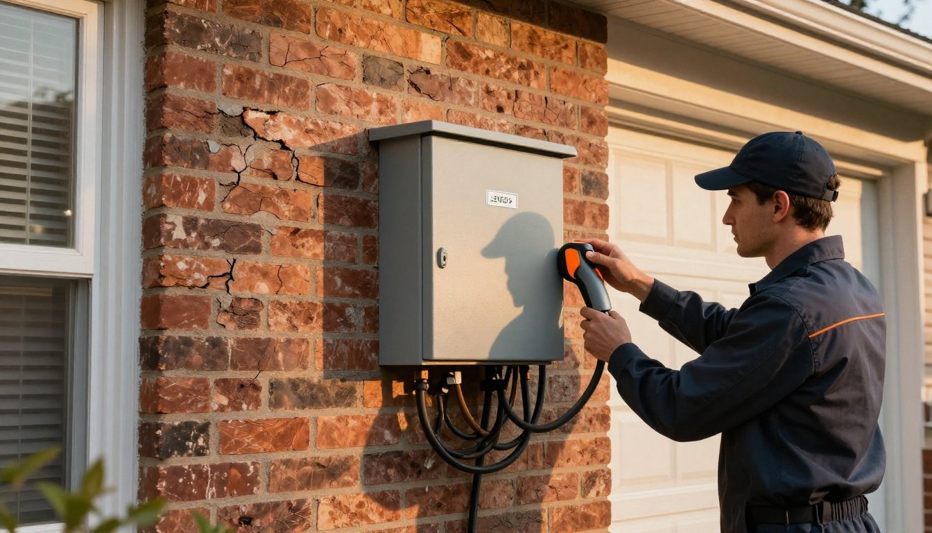
Cable Management, Mounting, and Weatherproofing

Planning cable management, mounting, and weatherproofing guarantees a 240V Tesla outlet stays safe, durable, and code-compliant. Route conductors in EMT or PVC conduit with Hidden routing where permitted; maintain gentle bend radius and install strain relief. Mount the receptacle/back box between 18–48 inches, plumb and anchored to studs or masonry. Use NEMA 3R/4X weatherproof covers outdoors, create a drip loop, and seal penetrations with UV-rated caulk. Apply Cable labeling at both ends, torque lugs per manufacturer, and verify GFCI protection and required clearances.
- Use corrosion-resistant fittings, anti-oxidant on AL, stainless hardware, and dielectric grease on terminals.
- Keep 36-inch working clearance; avoid tripping hazards with cord hangers.
- Install cord hooks/holsters; prevent connector strain and off-ground storage.
- Inspect gaskets, caulk, and fasteners annually; replace weathered components.
Future-Proofing: Load Sharing, Smart Features, and Upgrades

Although you’re installing a single 240V outlet today, design the branch circuit and raceway for tomorrow’s loads: size conduit for future pulls (often 1 in. minimum), provide a dedicated homerun to the panel, and leave spare breaker spaces for a second EV or a future hardwired EVSE.
Choose a receptacle location that can convert to a wall connector; feed it with 60A conductors in the conduit, but protect at 50A today per receptacle rating. Install a submeter or CTs for load management and NEC 220 load calculations. Select smart EVSE that supports load sharing, Wi‑Fi, OCPP, and demand-response. Plan solar integration with a gateway or microinverter API. Reserve service capacity and interconnection for V2G readiness, isolated transfer, and OCP. Label circuits and update one-line.
Conclusion
You’ve weighed 14‑50 versus 6‑50, checked panel capacity, and sized a 50 A circuit with 6 AWG copper under the NEC 125% rule. Pull permits, follow GFCI and clearance requirements, and use listed parts in enclosures. If panel work feels like heavy weather, hire a licensed electrician. Mount securely, manage cable, weatherproof, and set sensible charging limits. You’ll tuck the electrons in gently each night, while your installation stays safe, inspected, and ready for upgrades.