You want a J1772 Level 2 charger that’s fast, safe, and compliant. At 240 V and typically 16–48 A, it uses control‑pilot and proximity signals to set current and lock out hazards. But proper results hinge on NEC 625: a dedicated circuit sized at 125% of continuous load, UL‑listed EVSE, and GFCI where required—ideally installed by a licensed electrician. Here’s how to choose features, verify compatibility, and avoid costly mistakes.
Key Takeaways
- SAE J1772 Level 2 uses 208–240 V, delivering about 3.8–19.2 kW (~10–45 miles/hour), limited by your vehicle’s onboard charger.
- Install on a dedicated circuit sized at 125% of EVSE current (NEC 625); use UL‑listed equipment with GFCI and a licensed electrician.
- Common EVSE ratings 16–80 A; match connector/cable ampacity, pick 18–25 ft cold‑flex cables, and inspect latches, contacts, and holsters regularly.
- Tesla and NACS vehicles charge via certified J1772 adapters with proper CP/PP pass‑through; avoid stacking or unvetted adapters and confirm equal current ratings.
- Use smart scheduling (TOU), OCPP load balancing, secure timekeeping, and annual verification; typical hardware costs $350–$800, installation $500–$2,000+.
Understanding the J1772 Standard

While often called “Type 1,” SAE J1772 is the North American AC charging standard that defines the connector, signaling, and safety controls for Level 1 (120 V) and Level 2 (208–240 V) EV charging. It specifies a five-pin interface with control pilot and proximity circuits, enabling handshake and current limits via PWM. You’ll see EVSE advertise 16–80 A at up to 240 V, with monitoring and GFCI per UL 2231/2594. The duty cycle tells your car the amperage; you must size branch circuits per NEC 625 continuous-load rules. As Standards Evolution progresses, revisions add fault detection, arc mitigation, and state-diagram clarifications. Conduct Interoperability Testing to verify connectors, latch force, signaling timing, and EMI robustness across vendors, minimizing nuisance trips and ensuring reliable start/stop behavior.
Vehicle Compatibility and Tesla Integration

How do you guarantee cross-compatibility between J1772 Level 2 EVSE and today’s vehicles, including Teslas? Start with the standard: SAE J1772 defines connector geometry, pilot/proximity signaling, and latch behavior, so the car reads the EVSE’s available current via duty cycle and enforces it. Verify Certification requirements: UL 2594/2231, FCC Part 15, and NEC Article 625 compliance reduce shock, fire, and EMI risk. For Teslas, use a J1772‑to‑Tesla adapter or a NACS-to-J1772 solution; both map control pilot and proximity correctly without altering safety interlocks. Avoid unvetted adapters or firmware that layer Proprietary protocols atop J1772. Confirm ground monitoring, GFCI, temperature sensing, and contact welding detection. Check OEM compatibility lists and firmware release notes. Document commissioning tests: continuity, insulation resistance, CP/PP states. Log results for traceability.
Charging Speeds: Level 1 Vs Level 2 Vs DC Fast

Because charging rate hinges on voltage, current, and your vehicle’s onboard charger, you should match the standard to your use case and electrical capacity.
Level 1 (120 V, 12–16 A) ~1.4–1.9 kW, adds 3–5 miles/hour. Overnight top-ups. Level 2 (240 V, 16–48 A, 3.8–11.5 kW (some 80A 19.2 kW) limited by onboard charger; 10–45 miles/hour; ideal daily. DC fast: 50–350 kW, bypasses onboard charger; 10–80% in 20–40 minutes; speed tapers with state-of-charge and temperature. Safety: use dedicated circuits, GFCI where required, UL-listed equipment, NEC 80% continuous-load rule, monitor cable/breaker heat. Battery longevity: prefer Level 2; minimize frequent high-SOC fast charging; precondition in cold. Charging etiquette: leave when you’ve hit target, avoid occupying higher-power ports unnecessarily, share during peak demand. Match rates and panel capacity.
Connectors, Adapters, and Cable Options

Why do connectors and cables matter for J1772 Level 2 charging? They govern safety, compatibility, and charging efficiency under SAE J1772. Choose UL-listed connectors with locking latches, temperature sensors, and silver-plated contacts that keep resistance low. Match cable ampacity to your EVSE rating (e.g., 32A, 40A, 48A); look for 8–10 AWG conductors, robust strain relief, and cold-flex jackets rated to -30°C to 60°C.
Adapters: use certified J1772-to-NACS or NACS-to-J1772 only when they carry current ratings equal to your EVSE and include proximity/pilot pass-through. Avoid stacking adapters.
Cable options: pick lengths 18–25 ft to reduce voltage drop and tripping risks. Seek IP54+ inlet caps, holsters, and storage solutions that prevent kinking. Prioritize material durability, UV resistance, and abrasion-tested sheathing; inspect regularly for safety.
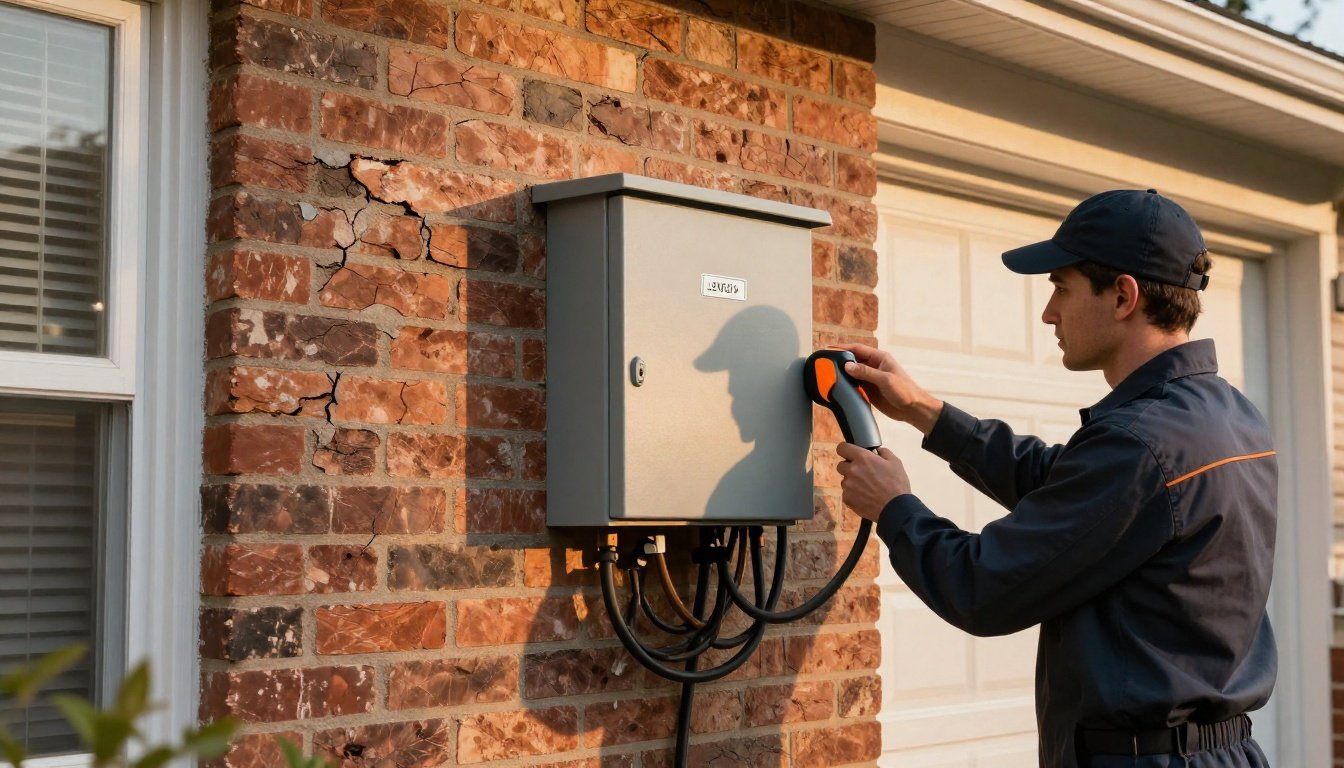
Home Installation and Power Requirements

You first verify electrical panel capacity with a load calculation (NEC 220) and space for a 2-pole 240 V breaker for the EVSE (NEC 625). Because EV charging is a continuous load, size the branch circuit at 125% of the EVSE current (EVSE draw ≤ 80% of breaker rating; NEC 210.20(A), 625.41). Practically, a 32 A EVSE uses a 40 A breaker and a 40 A EVSE uses a 50 A breaker; if the panel can’t support this, plan a service upgrade and use a licensed electrician with permits.
Electrical Panel Capacity
Before installing a J1772 Level 2 charger, verify that your service and panel can support a dedicated 240 V branch circuit sized per NEC. Start with a dwelling load calculation per NEC 220 to confirm available capacity on the service disconnect and panel bus. Check the panel’s bus rating and main rating; the EVSE adds a continuous load, so margin matters. Many homes with 100 A services are tight; 200 A services typically accommodate a 7–11 kW EVSE more easily. Confirm conductor ampacity, terminations, and panel space for a two‑pole position. If capacity is limited, consider a service upgrade or a properly rated subpanel. For Future proofing, evaluate potential second EVs, higher kW units, or load management-ready panels to avoid later rework and cost.
Circuit Breaker Sizing


Once the service and panel can support the load, size the branch-circuit breaker to the EVSE’s continuous load per NEC 625 and 210.20(A): treat EV charging as continuous and apply 125% to the nameplate output current. Example: a 32 A EVSE requires a 40 A breaker; a 40 A EVSE requires 50 A. Size conductors for the 125% load per NEC 310.16 and termination temperature ratings. Use a breaker listed for your panel, with adequate interrupting capacity for the available fault current (typically 10 kAIC; verify). Choose trip curves suitable for EVSE inrush and continuous duty—thermal-magnetic, not instantaneous-only. For receptacle-fed EVSE, apply 210.8 GFCI; hardwired units often integrate GFCI. Coordinate AFCI as required, label the circuit, torque terminations per manufacturer specs, and document installation.
Smart Features and Energy Management

With Wi‑Fi and app control, you monitor kWh and amperage in real time, set limits, receive security/firmware updates, and—if OCPP-enabled—tie into utility programs. Dynamic load balancing automatically allocates current to keep the circuit under panel limits and the 80% continuous-load rule (NEC), reducing thermal risk and nuisance trips. You schedule charging for off‑peak TOU windows or demand‑response events to cut costs and smooth load while maintaining SAE J1772 interoperability.
Wi-Fi and App Control
Although a J1772 Level 2 charger can run as a basic plug-and-charge device, Wi‑Fi and app control add standards-based energy management and safety functions. You can schedule charging to off-peak windows, set current limits, and view kWh, session time, and cost estimates. Look for OCPP 1.6J/2.0.1 support, UL 2594/2231 listings, and secure OTA Firmware Updates. Apps should enforce WPA3 Wi‑Fi, TLS 1.2+ encryption, and optional MFA. Vendors must state data collection scope; mitigate Privacy Risks with local-only modes, consent, and data deletion. Real-time alerts for ground-fault trips, overtemperature, or stuck relays improve safety. Accurate metering (±1–2%) enables utility rebates and verifies performance. Guarantee fail-safe operation if connectivity drops: charging should continue under SAE J1772 pilot limits, with logs syncing when online. Test failover periodically.
Dynamic Load Balancing
Because panel capacity and tariffs are finite, dynamic load balancing lets you allocate amperage across one or more J1772 Level 2 ports in real time without exceeding feeder, breaker, or service limits. You’ll use CTs and meter data to cap aggregate load, then apportion current per port using SAE J1772 pilot limits. OCPP backends can enforce site setpoints aligned with utility tariffs or demand charges, while NEC 625 and 220 calculations guide safe diversity factors. Prioritize circuits by vehicle state, connector rating, or user policy. For fleets, aggregator participation enables grid services without tripping protection.
| Feature | Benefit |
|---|---|
| CT-based metering | Accurate kW/kVA caps |
| Per-port pilot control | Standards-compliant current sharing |
| OCPP policies | Remote limits, analytics |
| Fault handling | Safe fallback, disconnect |
Document settings and verify protections annually.
Scheduled Charging Times
During off‑peak windows, scheduled charging aligns J1772 Level 2 sessions with utility TOU tariffs and site demand limits to cut cost and peak kW. You’ll program start/stop times based on commute patterns, battery SoC, and facility kW caps, then let the EVSE enforce them via SAE J1772 control pilot. Use OCPP or vendor apps to sync tariffs, holidays, and weekend charging. Set departure-ready targets (e.g., 80% by 7:00) and stagger multiple ports to meet NEC service limits. Verify UL-listed equipment, secure time sources (NTP/GPS), and fail-safe defaults that halt charging on clock drift. Track kWh, demand, and GHG using interval data. Document schedules, audit logs, and user overrides. Update firmware to patch timekeeping, daylight-saving, and utility rate-table issues. Test scenarios before broad user rollout.
Costs, Rebates, and Safety Considerations

When you budget for a J1772 Level 2 charger, look beyond the sticker price to total installed cost, available incentives, and required safety standards.
Factor hardware ($350–$800), installation ($500–$2,000+), permit and inspection fees, and panel upgrades.
Confirm warranty coverage and ask your insurer about insurance implications for new electrical work.
Leverage incentives: utilities offer $200–$1,000 rebates; some regions provide off-peak credits; a federal tax credit may cover up to 30% of costs if eligible.
Verify pre-approval and documentation requirements.
Prioritize safety and compliance: require a licensed electrician, NEC 625 load calculations, a dedicated 240V circuit sized per the 125% continuous-load rule, and UL 2594/2231-listed equipment with GFCI protection.
Specify NEMA 3R/4 enclosures for outdoors, torque labels, and cable management.
Test commissioning and keep records.
Conclusion
You’ve got the roadmap: a J1772 Level 2 delivers 240 V AC at 16–48 A, negotiates current via control‑pilot/proximity, and plays by NEC 625. Size the branch circuit at 125% of continuous load, use UL‑listed EVSE, GFCI where required, and hire a licensed electrician. Pick smart features—scheduling, load balancing, OCPP—and track energy. Verify cable/adapters, rebates, and warranty. Do it right and your garage becomes a safe, standards‑tuned pit lane for data‑driven charging today and tomorrow.