Like a well-tuned microgrid, you orchestrate PV arrays, MPPT, DC bus control, inverters (UL 1741/IEEE 1547), storage with BMS, and EVSE that speaks OCPP/ISO 15118. You design to NEC, meter accurately, secure firmware, and validate via commissioning tests and SCADA monitoring. You optimize tariffs, export limits, and demand charges while maintaining resilience. But the real gains appear when sizing meets interconnection constraints and duty cycles—what shifts that balance?
Key Takeaways
- Solar charging stations use PV arrays and MPPT-controlled DC buses to deliver stable EV power, with storage smoothing variability and supporting islanding/black start.
- Control and safety follow IEEE 1547, UL 1741, IEC 61851/ISO 15118, with OCPP session management, metering compliance, and IEC 62443 cybersecurity.
- Core components include PV modules, inverters/charge controllers, energy storage (LFP/NMC), racking, protection, certified per IEC/UL standards and sized for site irradiance and load profiles.
- Design uses 15-minute EV session profiles mapped to irradiance, performance ratio, temperature derating, with P50/P90 simulations to size arrays, storage, and inverter loading.
- Successful sites balance insolation, grid interconnection capacity, traffic and dwell patterns, ADA access, and resilience features like islanding, OpenADR demand response, and V2G readiness.
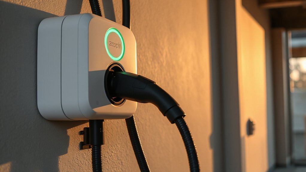
How Solar Charging Stations Work

While sunlight varies by the minute, a solar charging station converts irradiance into stable charging power through a controlled DC bus. You orchestrate energy flow by enforcing setpoints, monitoring voltage, current, and state-of-charge in real time, and applying grid-interaction limits per IEEE 1547 and interconnection rules. You expose status and pricing through a user interface, authenticate drivers, and govern session management under OCPP, while charge control follows IEC 61851 and, for Plug&Charge, ISO 15118. You schedule loads to minimize demand spikes, prioritize safety interlocks, and log metrology per MID or ANSI C12. You validate insulation, ground fault thresholds, and temperature derating, then issue start/stop commands only when all prerequisites pass. You retain audit trails, push telemetry, and enforce cybersecurity baselines such as IEC 62443.
Core Components and Technologies

You’ll select photovoltaic modules by efficiency, temperature coefficient, degradation rate, and certifications (IEC 61215/61730), matching array voltage/current to site conditions and BOS limits. You’ll size energy storage to the load and autonomy targets, defining chemistry (e.g., LFP vs NMC), cycle life, C-rate, round‑trip efficiency, and safety compliance (UL 9540/1973, IEC 62619). You’ll specify inverters and charge controllers for MPPT range, conversion efficiency, grid/standalone modes, protections, and standards compliance (IEEE 1547, UL 1741 SA, IEC 62109), ensuring coordinated control.
Photovoltaic Panel Selection
Because PV modules determine array voltage, energy yield, and safety, their selection must align with the electrical design and applicable certifications. You’ll size strings to keep Voc within inverter limits at lowest temperatures and verify Isc within input ratings. Verify IEC 61215/61730 or UL 61730, fire class, and mechanical load. Compare efficiency, bifacial gain, temperature coefficient, NOCT, and degradation. Evaluate module aesthetics, frame materials, connectors, junction-box IP rating, and potential-induced degradation resistance.
- Match STC ratings to site irradiance and soiling profiles accurately and maintenance.
- Choose glass/glass for durability; confirm hail, wind, snow certifications compliance.
- Verify MC4-compatible connectors and 1500 V listing for longer strings.
- Check fire classification with racking; avoid mismatch with building code.
- Review warranties: product, linear performance, and authorized service channels availability.
Energy Storage Systems
After establishing module string voltages and inverter limits, specify the energy storage system so it integrates electrically and meets code. Select chemistry based on cycle life, temperature range, C-rate, and safety. Validate compliance with NEC 706, UL 9540/9540A, UL 1973, NFPA 855, and IEC 62619. Size usable capacity from load profiles, autonomy targets, depth-of-discharge limits, and round-trip efficiency. Specify DC bus voltage windows, fault current withstand, isolation, and enclosure ratings (NEMA/IP). Integrate BMS data paths, disconnects, overcurrent protection, and thermal management. Address Policy Frameworks that govern siting, interconnection, and fire codes, plus end-of-life Recycling Programs.
| Parameter | Target |
|---|---|
| Usable Capacity | kWh meeting autonomy |
| Max C-rate | Charge/discharge limit |
| Voltage Window | Min/Max pack V |
Document maintenance intervals, monitoring points, and commissioning tests for acceptance, plus periodic audits.
Inverters and Charge Controllers
While PV modules and batteries set the energy foundation, inverters and charge controllers define conversion, protection, and grid-interactive behavior.
You select inverter topologies (string, central, or hybrid) that meet IEC 62109 safety and IEEE 1547 interconnection, then pair them with controllers implementing MPPT algorithms for stable harvest.
Specify DC-AC efficiency, low THD, anti-islanding, surge withstand, and cybersecurity for remote updates.
On the DC side, set array voltage windows, battery chemistries, and charge profiles per UL 1741 SB and manufacturer limits.

Engineer thermal management, cable sizing, and grounding to sustain reliability in high irradiance and ambient heat.
- Validate ratings against load and climate.
- Configure DC/AC OCPD, RCD, arc-fault protection.
- Tune MPPT sweep rates to stabilize.
- Monitor heatsinks; log temperature derating.
- Verify firmware, logs, alarms securely.
Sizing and System Design

You quantify charging demand by profiling load types, duty cycles, concurrency, and efficiencies, then calculate Wh/day and kW peak using documented assumptions per IEC 60364-7-712 or NEC 690. You size the PV array to meet energy and peak power targets based on site POA irradiance, performance ratio, temperature derating, and worst-month criteria. You size storage for required autonomy and response, accounting for C-rate, round-trip efficiency, usable DoD, and ensuring compliance with UL 9540/9540A and IEEE 1547.
Load Estimation Basics
How should you quantify demand for a solar-powered charging station? Start by defining service classes, temporal resolution, and metrics: average power, peak kW, daily kWh, coincidence factor, and power quality limits. Use historical data or pilot metering to bound load uncertainty, and apply sampling methods aligned with IEC 62559 use-case modeling and IEEE 1459 power definitions. Document assumptions, seasons, and growth. Set data quality thresholds, and track anomalies with reproducible, versioned datasets consistently.
- Profile sessions by connector type, charge rate, dwell time, and simultaneity.
- Build 15‑minute load profiles; compute mean, P95, P99, and maximum.
- Incorporate diversity factors, noncoincident peaks, and demand response policies.
- Validate with short-term metering campaigns; correct for weather, weekdays, and events.
- Quantify future scenarios: fleet mix shifts, utilization ramp, regulatory constraints.
Array and Storage Sizing
Given a quantified 15‑minute load profile, size the PV array and battery by mapping energy and power requirements to site irradiance, reliability targets, and interconnection limits. Convert the profile to daily kWh and peak kW, then apply plane‑of‑array irradiance, temperature‑corrected module efficiency, and balance‑of‑system losses to compute required DC capacity. Use Historical trends and Academic benchmarks to set capacity factors, degradation (0.5–0.8%/yr), and availability. Constrain inverter loading ratio (1.1–1.3) per IEEE 1547 interconnection and local feeder limits. For storage, derive autonomy hours from uptime criteria, set usable SOC window (e.g., 15–90%), and size for worst‑case seasonal minimum insolation. Validate voltage, C‑rate, and round‑trip efficiency against UL 9540/1973. Iterate with stochastic weather years to meet P50/P90 energy guarantees. Document assumptions and margins for compliance audits.
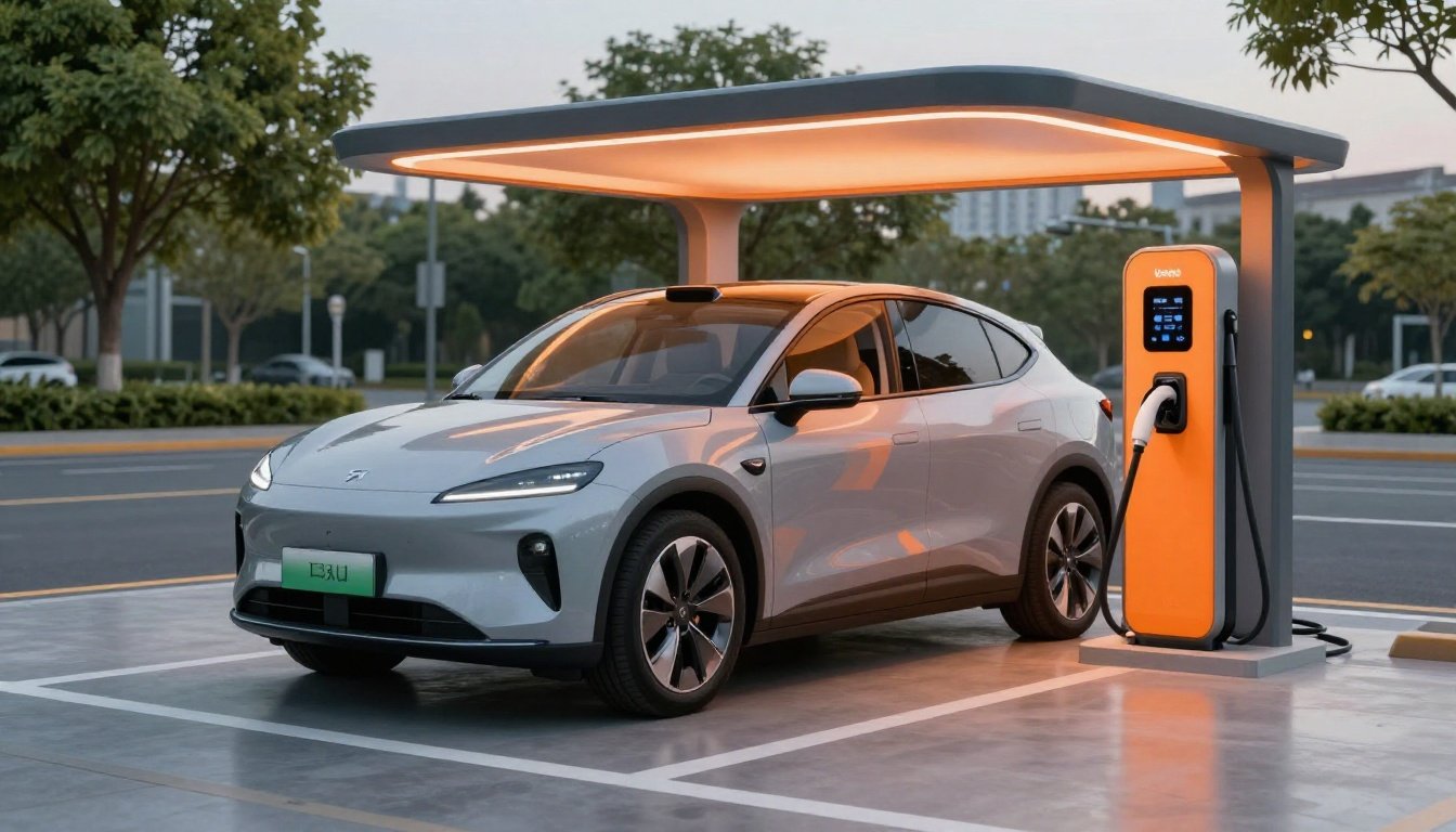
Site Selection and Use Cases

While site selection ultimately dictates performance and cost, it must align intended use cases with technical, regulatory, and operational constraints. You’ll evaluate insolation, grid interconnection topology, vehicular throughput, and safety setbacks against codes (NEC, NFPA 70, IFC) and zoning. Prioritize access, visibility, and Land Reuse opportunities (e.g., parking canopies, brownfields) while mitigating shading and geotechnical risks. For Emergency Resilience, provide islanding capability, clear egress, and proximity to critical loads.
Site selection drives performance—align use cases with codes, grid, access, and resilience.
- Validate solar resource via TMY data, drones, and shading surveys.
- Confirm utility capacity, fault levels, and protection coordination for safe interconnection.
- Assess traffic patterns, dwell times, ADA compliance, and signage for user flow.
- Verify soil, wind, and seismic parameters; apply ASCE 7, ACI 318.
- Provide lighting, CCTV, and cybersecurity per NEMA, IEC 62443 guidelines requirements.
Cost Breakdown and Return on Investment

Site selection decisions directly shape capex, opex, and your pro forma. Your capex spans PV modules, inverters, racking, EVSE hardware, switchgear, civil works, trenching, and interconnection per IEEE 1547 and NEC Article 690. Opex covers preventive maintenance, monitoring to IEC 61724, inverter replacements, software licenses, networking, insurance, and site leases. Quantify yields with TMY data, performance ratio, and degradation. Model charging revenue by utilization, tariff, and demand profiles. Compute LCOE and cost per delivered kWh to EVs; compare to tariff-blended revenue. Build a discounted cash flow with WACC, tax, and replacement reserves. Run Sensitivity Analysis on capex, utilization, irradiance, and downtime. Define KPI targets: payback, IRR, NPV, and Break even Timeline. Validate assumptions with pilot data and SCADA logs; update contingencies and spares budgets.
Incentives, Rebates, and Financing Options

How you stack incentives, rebates, and financing will drive net capex, WACC, and your tariff strategy. Map each mechanism to specific cost elements and timeframes, then model cash flows under conservative energy yield and degradation assumptions. Prioritize bankable instruments, documented to ISO 14064/IEC standards where applicable, to reduce perceived risk and lower pricing.
- Federal and state Tax Credits: monetize via transferability or tax-equity; reflect recapture risk and basis reductions.
- Utility or OEM rebates: treat as capex offsets; verify milestone, clawback, and M&V requirements.
- Performance-based incentives: discount for curtailment, uptime SLAs, and metering uncertainty.
- Debt instruments: Green Bonds or ESG-linked loans; align covenants with PPA floors and DSCR targets.
- Grants and carbon revenues: stack cautiously; avoid double-counting, permanence conflicts, and audit gaps and compliance lapses.
Installation, Permitting, and Interconnection

Although incentives shape the economics, you only bank them after you execute installation, permitting, and interconnection to code and utility standards. Begin with stamped engineering drawings aligning structural loads, conduit routing, and EVSE placement with NEC, IEEE 1547, and utility service requirements. Verify Local Ordinances on zoning, setbacks, signage, and parking modifications. Submit complete packages to the AHJ to compress Permit Timelines: site plan, one-line diagrams, fault current calculations, equipment cut sheets, and grounding details. Coordinate utility pre-application, interconnection studies, and meter upgrades; select export controls, relays, and protection settings per tariff. Schedule trenching, racking, and array wiring to meet inspector access and labeling conventions. Close with witnessed commissioning and utility permission to operate, then file incentive documentation. Retain as-built records for future audits.
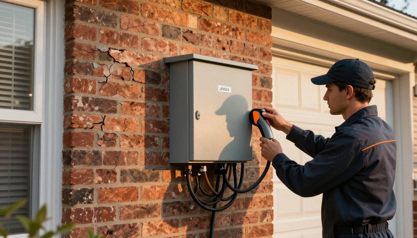
Operations, Maintenance, and Safety

Operating a solar EV charging station demands a formal O&M and safety program aligned to NEC, NFPA 70E, OSHA 1910/1926, and manufacturer instructions. You’ll standardize procedures, document configurations, and verify protective devices function as designed.
Operate solar EV charging with a formal O&M and safety program aligned to NEC, NFPA 70E, OSHA, and manufacturer instructions.
- Conduct Routine Inspections: torque checks, infrared scans, insulation resistance tests, and GFCI verification on defined intervals.
- Maintain cleanliness: clear modules, vents, and enclosures; manage vegetation and drainage to prevent faults.
- Calibrate and test: meters, relays, EVSE ground fault, and rapid-shutdown circuits using traceable methods.
- Implement Emergency Procedures: lockout/tagout, arc‑flash response, spill control for batteries, and first‑aid drills with posted contacts.
- Record, analyze, and act: log outages, alarms, and trend data; execute corrective maintenance and update as-built drawings.
Train authorized workers, limit energized work, and stock spares, PPE, and signage.
Future Trends and Smart Grid Integration

As utilities digitize distribution grids, solar EV charging stations must evolve into grid-interactive DERs that support flexible load, storage, and bidirectional power flows. You should implement IEEE 1547-2018 interconnection functions, OpenADR for automated demand response, and ISO 15118 for V2G, contract authentication, and smart charging. Leverage Dynamic Pricing via OCPP 2.0.1 tariff profiles and align dispatch with real-time locational marginal prices. Deploy predictive control using weather forecasts, SoC telemetry, and feeder constraints to minimize hosting-capacity violations. Coordinate with utility ADMS/DERMS through secure APIs, supporting IEEE 2030.5 or IEC 61850 mappings. Prioritize Cybersecurity Integration: NISTIR 7628 guidance, TLS 1.3, secure boot, signed firmware, role-based access, and continuous monitoring. Design for microgrid islanding, black start, and resilience under IEEE 2030.7/8. Audit supply chains and patch promptly.
Conclusion
You’ve seen how solar charging stations integrate PV, MPPT/DC-bus control, storage, and EVSE to deliver compliant, reliable power. Anchor designs to IEEE 1547, NEC, UL 1741 SA, and metrology requirements, and use OCPP/ISO 15118 for secure, interoperable control. Size for duty cycle and tariffs, verify with commissioning tests, and monitor KPIs. One visual benchmark: a 250 kW canopy offsets 350 MWh/year, avoiding 250 tons CO2e. Do this and you’ll optimize uptime, ROI, and grid services.